
Machine Component Design: Design of a Bearing and Gear for a Shaft-gear-bearing System
- Andrea Schultz
- Oct 2, 2017
- 2 min read


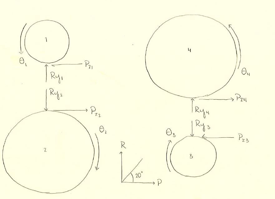
Project 6 of ME 480, Machine Component Design, focused on the analysis and design of a gear train. This project applied given course information to complete open-ended analysis, design, and selection of machine components. All sections of this project refer to the above gear train, with gear spacing shown in inches. The following assumptions were made:
To simplify manufacturing and inventory, gears 1 & 3 will be identical, as will gears 2 & 4.
The smallest gears must have a minimum of 12 teeth.
Each gear set has a 2:1 reduction.
The gear train experiences moderate shock, but less than 15 minutes every 2 hours.
The "Basic" Level of this project includes using the Boston Gear catalog to select the smallest center-to-center set of spur gears with a 20 degree pressure angle that can transmit the specified power if gear 1 rotates at 1200 rpm. In addition, the contact forces between the four gears were determined, both in magnitude and direction. By using T = P/omega dp = # of teeth/in of diameter, torque can be determined. By going through the catalog under a 20 degree pressure angle, a list of dp options can be made:
20 dp steel
20 dp CI
16 dp steel
16 dp CI
12 dp steel
10 dp steel
The 12 dp steel option satisfies both the 3.5 in pitch for gears 2 & 4 and the 1.75 in pitch for gears 1 & 3 (see calculations for this conclusion on the main page of Portfolio under Class Projects.) With this, I recommended a YD21 spur gear (from the catalog - this selection is highlighted at the very end of this post)for gears 1 & 3 and a YD42A for gears 2 & 4. A free body diagram (FBD) and an analysis of the stresses applied to the gears at their contact points can be shown below.

The "Medium" Level of this project includes completing shear, moment, and torsion diagrams, which can be shown below. By using the Boston Gear catalog again, appropriate 1600 series bearings for the shaft was selected since the radial loads on each bearing is known. A complete static analysis of the shaft was performed, finding the forces at each point as shown in the FBD. The torsional stresses within the shaft were also calculated in order to produce a moment diagram.
Overall, looking at the top view the maximum shear force is 162.06 lb between the centerline of gear 2 and the centerline of gear 3. The maximum moment is 297.06 in-lb at the centerline of gear 3 and the maximum torsion was also between the centerline of gear 2 and the centerline of gear 3 at 315.1 in-lb. At the front view, the maximum shear force is at -111.45 lb between the centerline of gear 3 and the centerline of the right bearing. The maximum moment was again at the centerline of gear 3 at 167.2 in-lb and the maximum torsion was the same as the top view. With respect to the bearing, I recommended a 1616DS bearing with an inner diameter of 0.5 inches.


Comments